
Looking to understand more about Canbus communications? Not a nerd but need or want to understand canbus for your project or build? You have come to the right place.
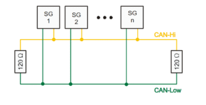
HISTORY AND GENERAL KNOWLEDGE – Going to keep it short and sweet. Canbus was developed in 1983 by Robert Bosch for use in automotive networking. It did not see widespread use until the U.S.A. government mandated use in vehicles sold in the U.S.A. starting in 2008. Canbus at its core is a twisted pair of wires with “termination resistors” at the ends of the network, either in the modules themselves or externally in the harness wiring itself. The twisted pair wire network goes from module to module to both “broadcast” information and also send/receive information depending on how the manufacture coded the controllers on the network. The two network wires are CAN High and CAN Low, also known as CAN+ and CAN-, CAN H and CAN L, etc. At network rest but with the modules on the network powered up, both wires have 2.5v on them, and CAN High will go up to 4+ volts and Can Low will go down to 1v or lower when a message is being transferred. Being this is a intro document I will not go into the actual composition of the canbus message and the differential voltages however with that said, the messages are being transmitted when the network is not at rest. You CAN NOT test canbus networks with a DVOM. You can test the individual wires with a DVOM for continuity, but in order to see any network issues it is REQUIRED to have a oscilloscope.
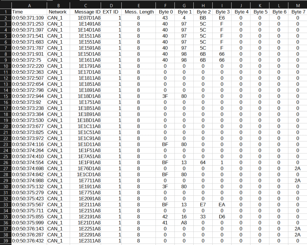
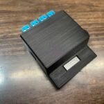
MESSAGE SPEEDS AND MESSAGE STRUCTURES – Here we can see the basic structure of a Canbus network. This specific one was recorded using the Twisted Builds LLC Canbus logger, of which was connected to a Holley Terminator X ECU. So again, introduction and information you need to know coming from the gearhead side of things – You will encounter different styles and speeds of Canbus systems in modern vehicles. We have medium speed Canbus (MS-CAN), High Speed Canbus (HS-CAN), Flexible Datarate Canbus (known as Can-FD), Flexray CAN – which is outside the scope of this article.
Lets first talk about “Regular” Canbus networks. Regular Canbus networks have on average three different normal speeds. The first two speeds are normally listed as Medium and High speed. Most automotive manufactures consider Medium speed at 250kbps (kilobits per second) and High Speed at 500kbps. The higher the speed, the faster the communication is. Now another speed you can encounter with “regular” canbus is 1mpbs or 1 megabits per second. The Holley Term X canbus log posted above is a module that communicates at the 1mbps canbus speed. When you are dealing with the automotive aftermarket, or most vehicles prior to 2020, most of the modules you will encounter talk at one of these three speeds. Something important to note is you can not intermix canbus speeds on a single network. This means, if you have a module that is talking at 250kbps (medium speed), you can’t wire that to a network that has a module talking at 500kbps, or 1mbps, etc because it will cause a network failure. If you have modules that you need to talk to one another, that are on different network speeds, you have to use what is called a “gateway” module that changes the network speed and or message for you. More about gateway modules later.
All Regular canbus networks can have standard or extended message ID’s. Think of this as the phone number of the message. Message ID’s are in HEX, but can be displayed in decimal. With that said though, I recommend getting used to doing message ID’s in HEX. HEX, is a base 16 system, so 0-9 then A-F. Standard canbus ID’s can have up to four decimals so the “phone number” can be 0000-FFFF. Extended message ID’s can have 00000000-FFFFFFFF which gives the module programmers way more “phone numbers” or message ID’s to work with. Canbus is primarily a broadcast network structure which means, all messages for the most part are just broadcasted. All modules on a network will broadcast a message, then the modules that need that information will filter out the messages by the message ID (phone number) and then use that data accordingly. After the message ID you get the message length – shown above in the recording as “Mess. Length”. This allows all the modules on the network receiving the broadcast message how long the message actually is for this message ID, so they know when the message data transfer is over. Talking about data, Regular canbus networks can have up to 8 usable data bytes. Canbus works on a 0 index so you can have up to 0-7 bytes in a message that have data in them, and each one of those bytes has a byte of data which is 00-FF or in decimal we understand, each message byte can have a internal value of 0-255. This is how data is broadcast from module to module. Lets take RPM for example. There are multiple ways of broadcasting RPM but a simple one I’ve ran into is using 2 bytes of a canbus message to output the engine RPM. Being engine RPM does not have a decimal and on most vehicles is not expected to have more than 4 numbers, example 9,999RPM, some manufactures will split the first two numbers of RPM from the last too, then broadcast that over two message bytes. So for the RPM example, we could have message ID 0x0089 that in byte 0 had a value of 24, and byte 1 value had a value of 89. If you combine bytes 0 (24) and byte 1 (89) you would get 2,489 RPM. This is not how data is always broadcasted, but is one of the ways it can be.
Next, lets talk about CAN-FD or Flexible Data rate Canbus networking, which will be referred to as CAN-FD moving forward. CAN-FD is going to be used more and more in modern vehicles (2020 and later) until Flexray CAN becomes mainstream. CAN-FD came about from needing faster network speeds for transferring data as close to “real time” as possible between modules, along with the need of having more message byte payload space. First, lets talk about CAN-FD speeds. CAN-FD has two different parts of its message that are sent at two different speeds, on the same twisted pair network. Yes, I typed that right and it takes a second to understand. The First part of a CAN-FD message is called Arbitration. Most of the Arbitration make up is outside the scope of this post, however what you need to know is the message ID, message length and data speeds are broadcast within the CAN-FD arbitration. Arbitration speeds mimic “Regular” canbus speeds, so you can have arbitration speeds at 250kbps, 500kbps, 1mbps, etc but normal cap on the arbitration speed is 1mbps. As mentioned earlier, the data speed is sent over the network during the arbitration part of the CAN-FD message. This speed is “Flexible” depending on programming, network load, etc. In most instances I’ve ran into, this value has been fixed and can be anywhere between 1mbps to 8mbps. After the Arbitration part of the message is sent, the data payload is sent. The data payload is being sent at a faster speed than the arbitration part of the message which means it will look different when using a oscilloscope on a CAN-FD network. Data on a CAN-FD message can be up to 64 bytes long. Again, CAN works on a 0 index so we have data being transferred between bytes 0-63. This extra message space per message ID allows for more data to be transferred faster, and in modern cyber security requirements, can also be with message keys or encryption. With all this said, CAN-FD for the most part is not used in the automotive aftermarket yet at the time of writing.
Flexray CAN – which is entirely out of the scope of this article however with that said, at the time of writing this article I do not know much about Flexray CAN outside the fact that it can have up to 254 bytes per message (0-253) and it is even faster than CAN-FD. At the time of this article, Flexray CAN is not used in the automotive aftermarket at all and shouldn’t be for the foreseeable future. I will update this article if that changes.
WHY DOES ALL THIS MATTER – So before we can run, we have to crawl, then walk. As a gearhead myself into oddball swapping or bespoke builds, on the electrical side of things you have to know what modules your attempting to make work together are doing. What speeds the canbus networks on them are communicating at, which canbus type in use, etc. Most canbus systems are not plug and play. There are aftermarket modules out there that allow you do build your own definitions for integrating with factory equipment, and there are times you have to figure it out on your own. This introduction is not written to be a all encompassing article on canbus but more of a introduction to the basics of what is going on, at its core how the network works and what you need to look out for when performing swaps.
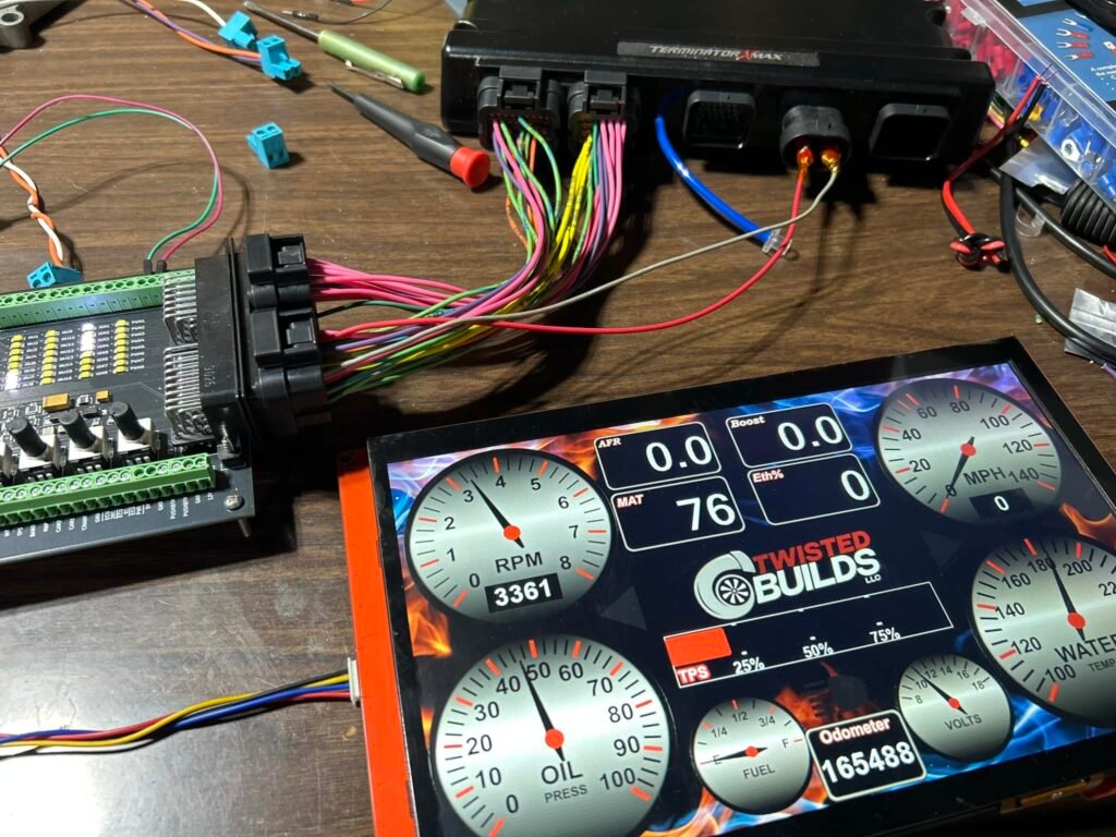
Coming next to the Tech Corner will be breaking down and reverse engineering network messaging to setup commercially available gateway modules or setup computers (MaxxECU, Motec, etc) for integrating with factory hardware, etc. Stay tuned for that and thank you for reading. If you have any feedback, please email me dale@twistedbuilds.com.
Dale
Overview image by By Stefan-Xp – Own work, CC BY-SA 3.0, https://commons.wikimedia.org/w/index.php?curid=3607670
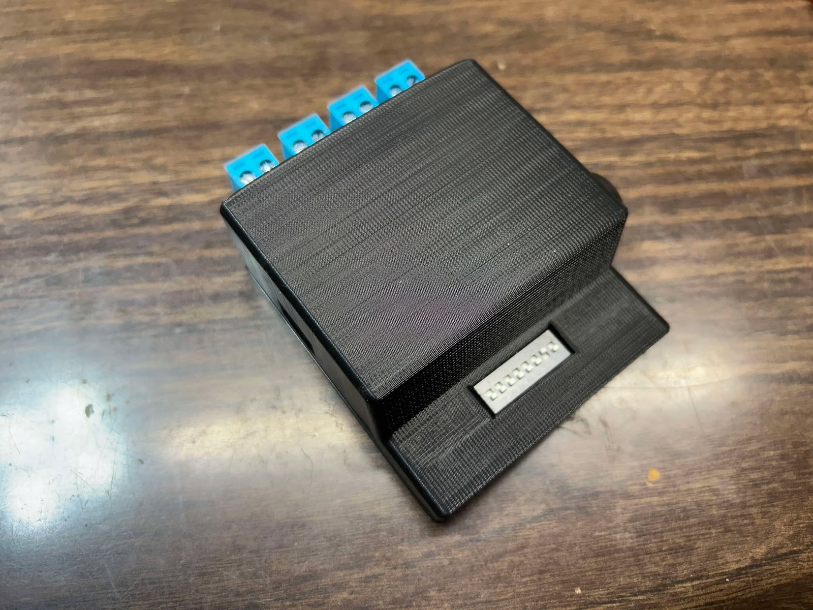
Other Images by Dale Follett – Twisted Builds LLC.


Leave a Reply